
PLC-Based Master Control for Solid-State Transformer
Project Overview
This project focused on testing a PLC-based master control system for a Solid-State Transformer (SST) consisting of a three-stage power conversion system: a rectifier, Dual-Active Bridge (DAB), and inverter. The project was carried out as a collaborative effort, where my colleague developed the PLC-based master controller while I was responsible for the simulation model, real-time HIL implementation, and communication interface between the PLC and Typhoon HIL.
Core Contributions & Technical Execution
1. Real-Time SST Simulation Development
The Challenge: The SST requires coordinated operation of multiple power-conversion stages, making it necessary to develop a real-time simulation model capable of representing the rectifier, DAB, and inverter while responding to external master-control commands.
My Execution: I adapted an existing SST simulation based on an averaged-model approach for real-time execution on the Typhoon HIL platform. The individual converter models were adjusted to suit the requirements of the PLC-based control experiment, including the operating sequences and interfaces required for each conversion stage.
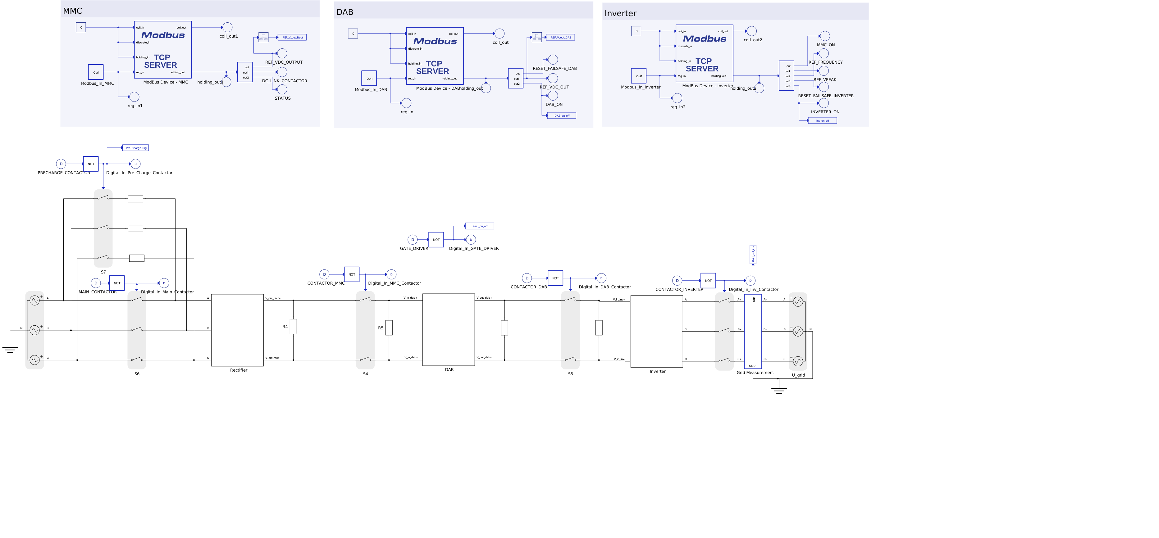
Figure 1. Solid-State Transformer system consisting of rectifier, DAB, and inverter stages.
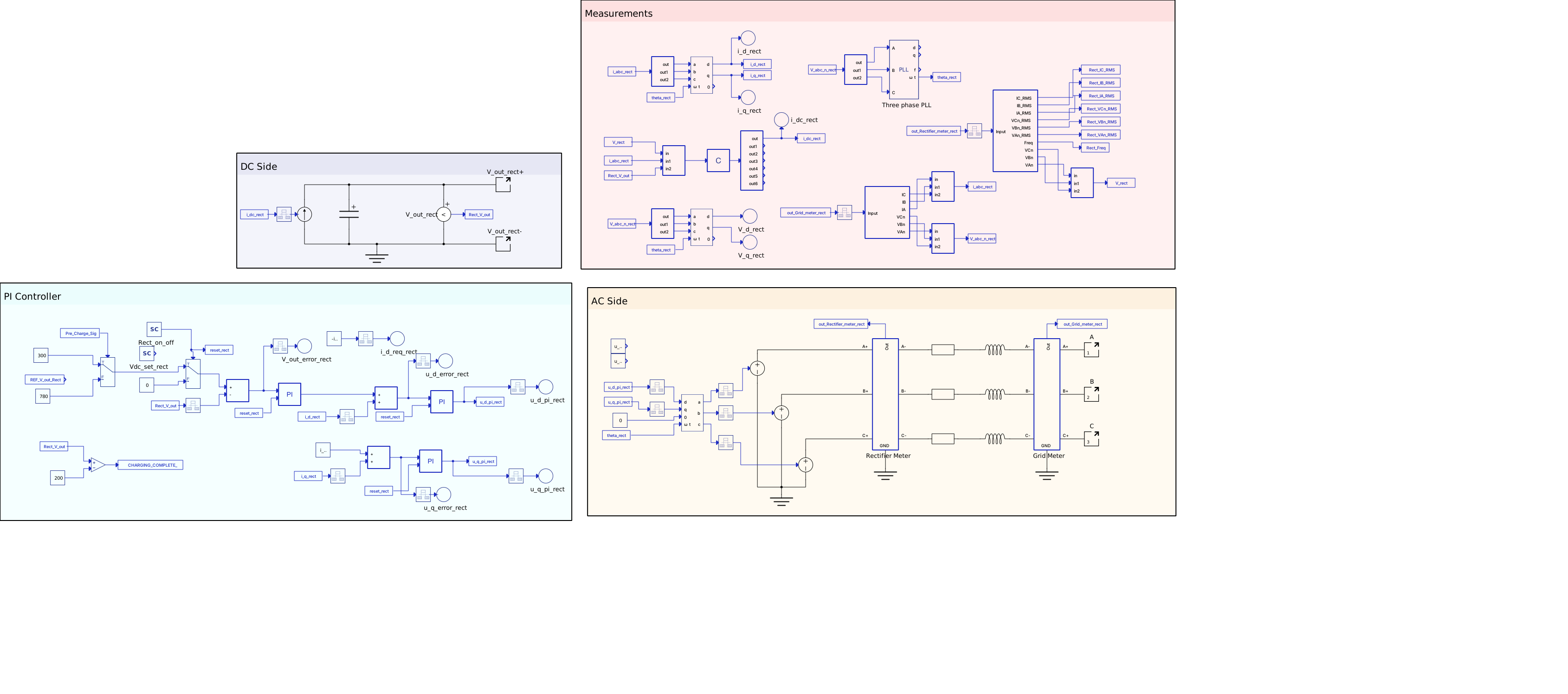
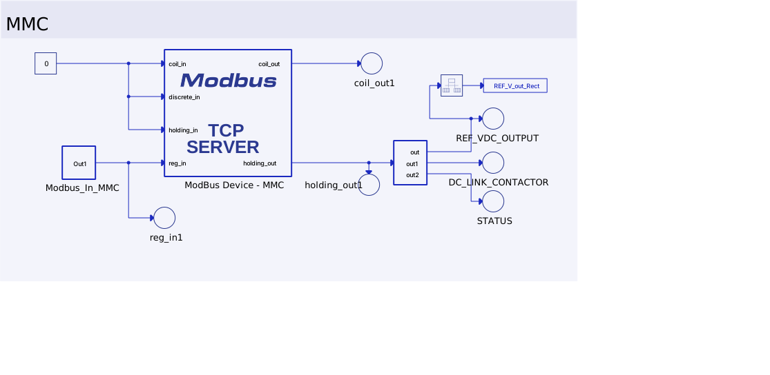
Figure 2. Rectifier simulation model and Modbus interface.
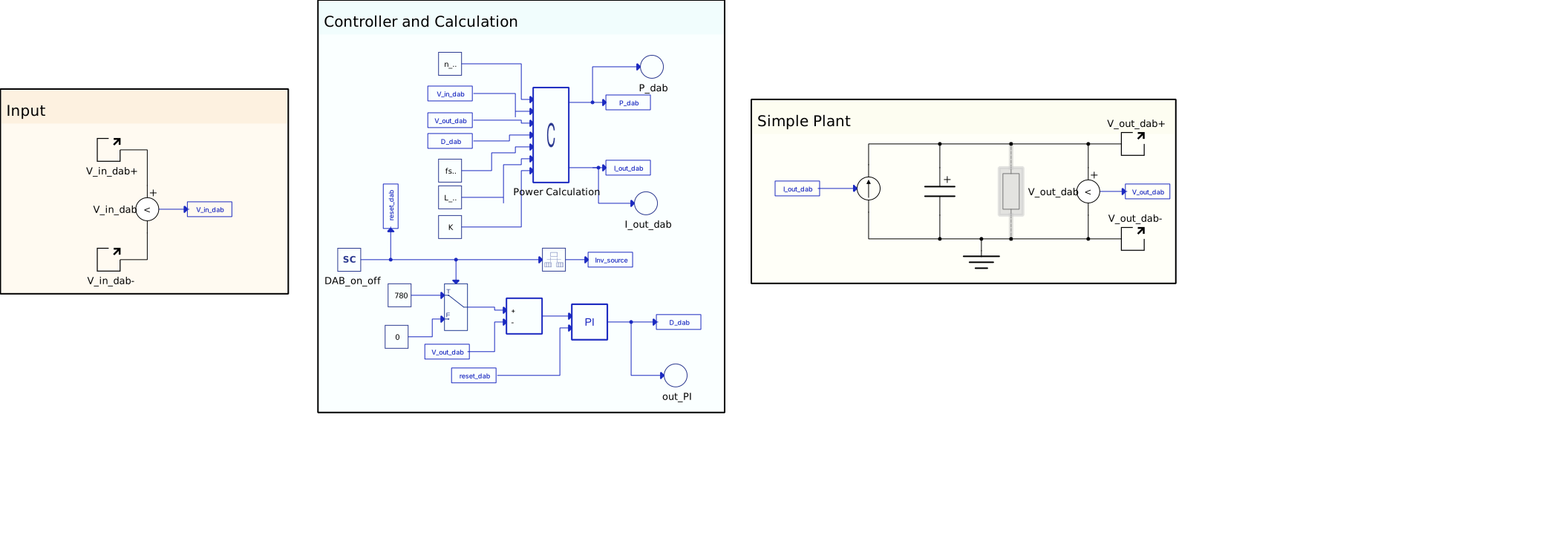
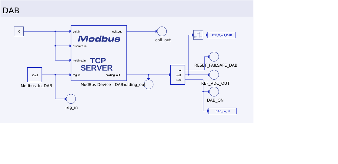
Figure 3. DAB simulation model and Modbus interface.
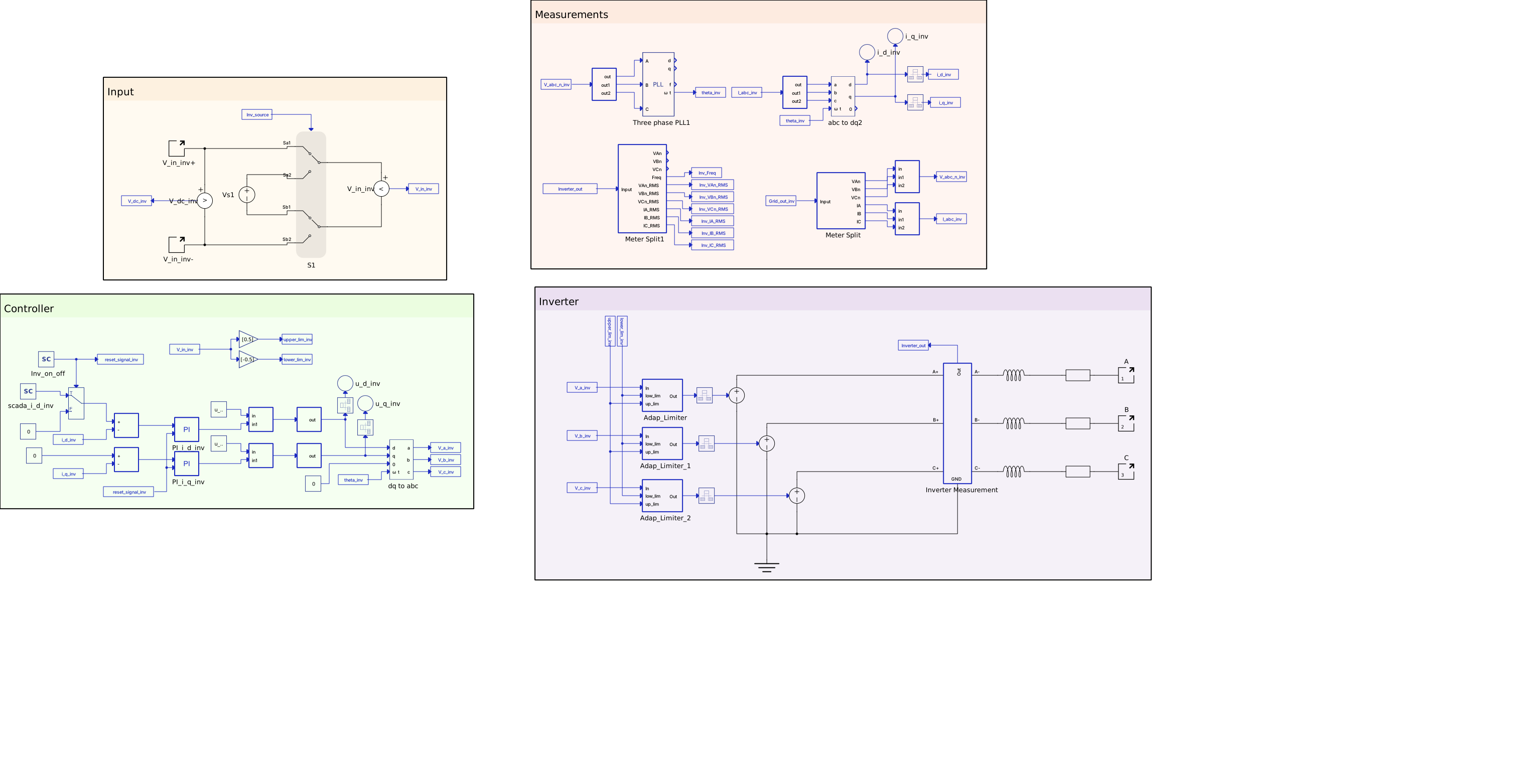
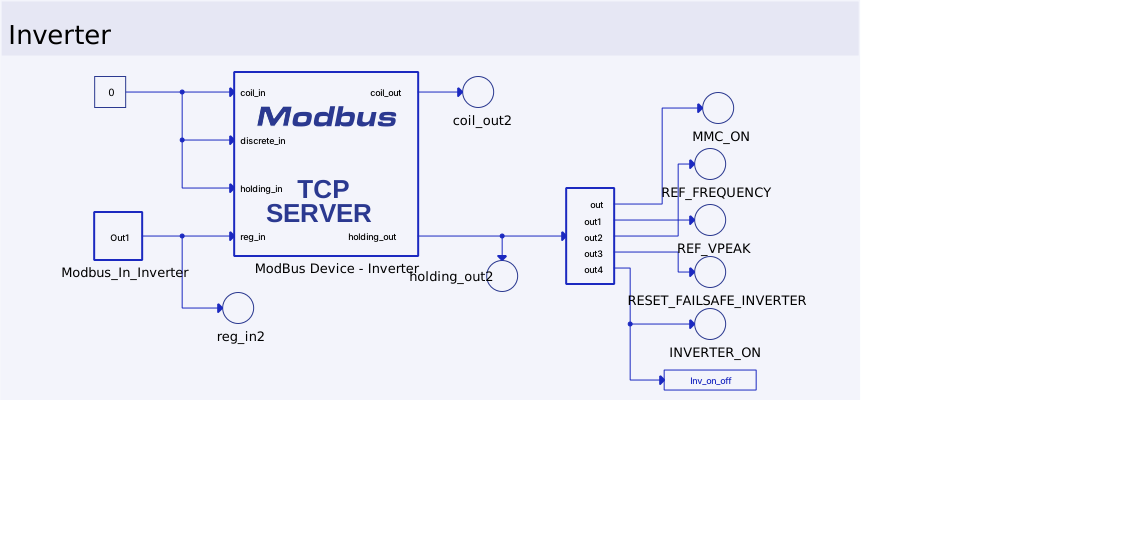
Figure 4. Inverter simulation model and Modbus interface.
2. HIL Validation of SST Operating Sequence
The Challenge: The complete SST system had to be tested according to its intended startup and activation sequence, requiring coordination between the three converter stages.
My Execution: I conducted the real-time HIL validation of the PLC master-control sequence, monitoring the converter responses and system variables through Typhoon HIL. The testing covered key operating stages, including dc-link precharging, DAB activation, and inverter synchronization, to verify that the PLC could coordinate the SST conversion stages correctly.
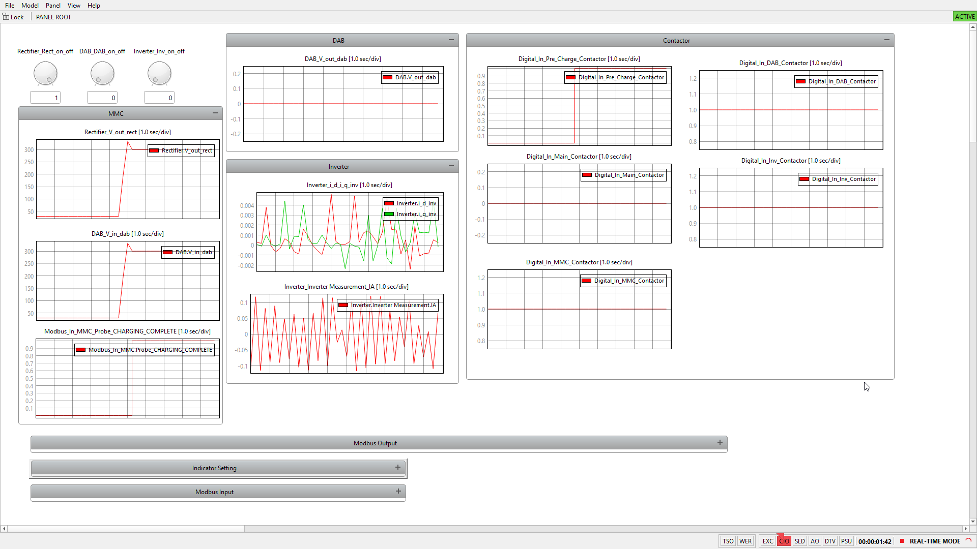
Figure 5. HIL result during the SST precharging sequence.
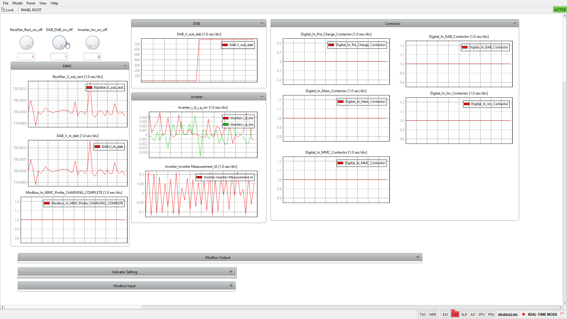
Figure 6. DAB activation during the SST operating sequence.
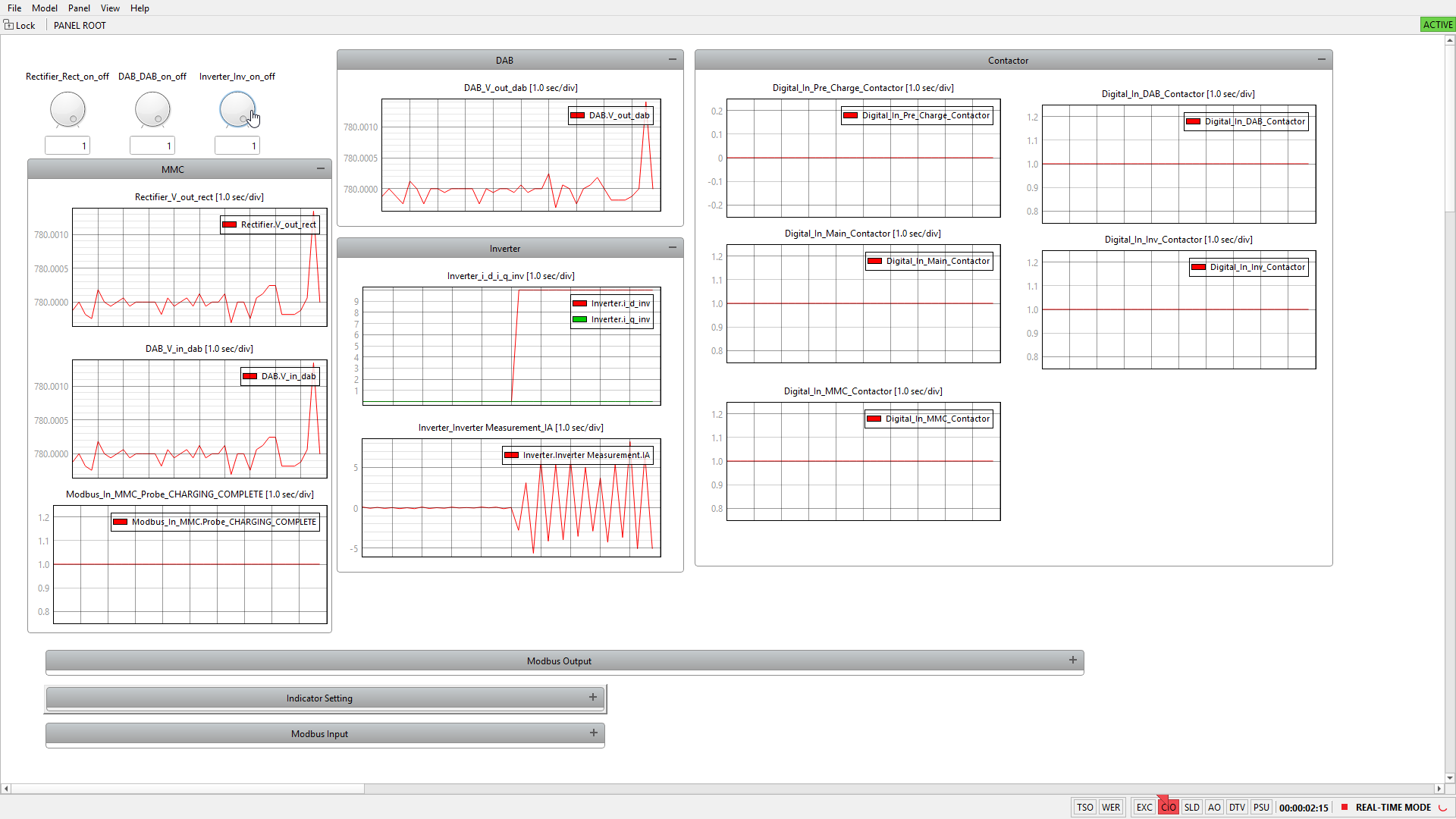
Figure 7. Inverter synchronization during real-time HIL validation.